Well, I've made my National Grid frequency monitoring thingy as I mentioned last week.
It's taken longer than it should have done, which I guess is the way with these things. It took me about 2 hours to get the comparator to output a signal greater than a noisy 200 mV signal. Who'd have thought I needed to pull up the output to 5 V? Not I, clearly. I'm sure I've never had to do that with comparators in the past. Will hunt my 2nd year group project schematic which used one :) Or wait for Joe to say, "Yeah, we needed one".
Then the 5V regulator decided to have a hairline fracture on one of its pins, so I needed to swap it out... which was fun. Involved canabalising one of my final year project boards... so two times desoldering (which I despise!).
Then I spent too long wondering why my RS232 reading thing on the server kept bombing out... I'm transmitting in binary and when contol characters got in the data they kept getting in the way :( Yeah, I should have known better.
Anyways, it's done... wooo yeah...
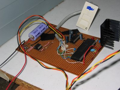
The RJ45 keystone isn't actually required, it's there so I can reprogram the PIC should I need to!
Oh, so you want some results?
The graph is updated every 1 minute and shows the deviation from 50 Hz over the last 20 minutes. A new data point is added to the dataset every 2 seconds (its value being the mean over the last 50 cycles).
The device isn't logging at the moment because it may or may not have been causing my server to crash! I'm checking to see if that is the case at the moment...
I'm not sure how accurate the device is - it does show different results that the DynamicDemand website, but who's correct, nobody knows. I'd like to have calibrated it with a signal generator at work, but it was in another lab, and I didn't fancy breaking 7 grand of kit with my Mickey Mouse circuit...:-/